What 100% Electrical Testing Really Guarantees in Custom Cable Assemblies
In August 2026, Ford filed a recall with the U.S. National Highway Traffic Safety Administration covering 148,663 Mustang vehicles from the 2024–2026 model years. According to the recall record (NHTSA 26V547000), ground connections in the engine-compartment wiring harness may fracture, which can lead to a loss of drive power or of other functions. The remedy was to replace the affected ground terminals.
Recalls like this show an uncomfortable fact about wiring: a harness can work correctly when it is built and still fail after months of heat, vibration and service. Production testing is designed to catch what is wrong at the moment of manufacture. Long-term reliability depends on many more decisions.
That is why "100% electrical testing" deserves a precise definition. This article answers three questions buyers and engineers ask us most often:
- What does 100% electrical testing actually verify?
- Which defects can pass electrical testing and still fail in service?
- What should you specify before production, so testing matches your application?
What "100% Electrical Testing" Actually Means
In cable assembly manufacturing, "100% electrical testing" means that every assembly is connected to a tester and checked before it moves on. This is different from sampling inspection, where a defined number of units is taken from a lot and examined in more detail.
Both approaches have a purpose:
- 100% testing is used for defects that can occur on any single unit, such as a swapped wire, an unseated terminal or a pinched conductor. Sampling cannot reliably catch random one-off errors like these.
- Sampling inspection is used for checks that are slower or require measurement, such as dimensions, materials against the drawing and workmanship. Sampling confirms that the process producing the lot is under control.
The common misunderstanding is to read "100%" as "fully verified". The figure describes how many units are tested, not how many characteristics are tested. A supplier that runs only a continuity check on every unit can honestly say "100% tested". So can a supplier that runs five separate electrical tests. The two statements mean very different things. Always ask which tests are included.
Continuity, Short, Miswire, IR and Hi-Pot: What Each Test Checks
The table below compares the five electrical tests most often used in cable assembly and wire harness production.
| Test | What it verifies | Typical defects caught | What it does not verify |
|---|---|---|---|
| Continuity (open circuit) |
Every intended circuit conducts within a resistance threshold | Broken conductor, missing connection, terminal not fully seated | Insulation strength; crimp quality beyond the resistance threshold |
| Short circuit | No unintended connection exists between conductors, or between conductors and shield | Stray strands, solder bridges, conductor pinched through insulation | Insulation breakdown that only occurs at higher voltage |
| Miswire (pin-to-pin) | Each pin connects to the correct pin on the mating end, as defined by the wiring map | Swapped wires, wrong cavity, reversed connector | Mechanical retention of terminals |
| Insulation resistance (IR) | Insulation resistance between isolated circuits meets a minimum value at a specified DC test voltage | Contamination, moisture, damaged or degraded insulation | Withstand against transient or high voltage |
| Hi-Pot (dielectric withstand) |
Insulation withstands a specified test voltage for a specified time without breakdown or excessive leakage current | Thin insulation spots, insufficient clearance, hidden insulation damage | Long-term aging, flex fatigue, vibration effects |
Continuity test
A continuity test applies a low voltage to each intended circuit and checks that resistance is below a set threshold. It is the foundation of electrical testing. It is also the easiest test to misread: a conductor held by only a few strands, or a marginal crimp, can still conduct well enough to pass.
Short circuit test
A short test checks every circuit against every other circuit, and against the shield where one exists, to confirm they are isolated. It catches manufacturing slips, such as a loose strand bridging two contacts, that would otherwise appear only after installation.
Miswire test
Miswire verification compares the measured connections with the programmed wiring map. Two wires swapped between adjacent pins will pass a continuity test, because both circuits conduct, but they will fail a miswire test. For assemblies with many positions or similar wire colors, this is one of the most valuable checks.
Insulation resistance (IR) test
An IR test applies a DC voltage between isolated circuits and measures the resulting resistance, typically in megohms. It shows whether the insulation is clean and intact. The test voltage and minimum value should be based on the cable rating and the application. They should also be agreed with the customer.
Hi-Pot (dielectric withstand) test
A Hi-Pot test applies a voltage well above normal operating voltage for a defined time and confirms there is no breakdown and no excessive leakage current. Hi-Pot is a test method, not a single fixed standard. The voltage, AC or DC, the dwell time and the leakage limit must be defined for each product, based on the cable's insulation rating and the customer's specification. Conditions that are too low prove little. Conditions that are too high can stress insulation that is otherwise good.
What Can Pass Electrical Testing but Still Fail in Service
Electrical tests verify an assembly at a single moment, usually on a bench, at room temperature and with the cable lying still. Many field failures develop later, under conditions the test does not reproduce.
The verification methods in the table below are general industry practice. Which ones apply depends on the application and should be defined in the product specification. NAVITAS's standard tests are described in How NAVITAS Tests Every Cable Assembly.
| Failure mode | Why electrical tests may not catch it | Typical verification methods (application-dependent) |
|---|---|---|
| Marginal crimp | Conducts at test time; may loosen or rise in resistance under vibration and thermal cycling | Crimp height and pull force checks, crimp cross-section on samples |
| Terminal or conductor fatigue | Develops after repeated flexing or vibration in the application | Flex or vibration testing that matches the real duty cycle; strain relief design |
| Insulation abrasion from routing | Harness is intact at shipment; damage occurs during installation or service | Routing and clamping review, protective sleeving, design review with the customer |
| Water ingress | Electrical tests are performed dry | Sealing design review; IP-rating validation where the application requires it |
| Overmold voids or poor bonding | Usually invisible to electrical measurement | Process control, visual inspection, sectioning of samples |
| Intermittent connection | May be closed during a static test and open only under movement | Dynamic testing while the cable is flexed (when the application requires it) |
For more on mechanical verification, see our overview of pull force testing in wire harness manufacturing. For sealed and strain-relieved designs, see overmolded cable assemblies.
Lessons from Recent Wiring Harness Recalls
Public recall records are a useful reminder that harness failures take different forms. The three examples below are taken from official NHTSA records. We cite only the defects described there. The records do not say how each harness was tested, and we draw no conclusions about the manufacturers' testing.
| Recall | Defect as described in the official record | Failure mode it illustrates |
|---|---|---|
| Ford, NHTSA 26V547000 (August 2026) 148,663 vehicles |
Engine-compartment wiring harness ground connections may fracture | Fatigue that develops in service |
| BMW, NHTSA 26V096000 (February 2026) approx. 58,713 vehicles |
An air-conditioning wiring harness near the cabin air filter may be damaged when the filter cover is installed, which can cause a short circuit | Routing and serviceability |
| GM, NHTSA 25V769000 (2025) model-year 2026 GMC Hummer EV |
The front passenger airbag connection in the instrument-panel harness may have an improperly crimped wire; the issue was identified during assembly | Crimp quality |
Each failure mode maps to a different control: application testing for fatigue, design review for routing, and process control for crimping. Electrical testing is an essential layer, but it is one layer.
What the EU Product Liability Directive Changes in 2026
The new EU Product Liability Directive, (EU) 2024/2853, replaces the directive that had applied since 1985. It applies to products placed on the market or put into service in the EU after 8 December 2026. The changes most relevant to cable assembly buyers are:
- Components are explicitly in scope. Liability can extend to defective components that are integrated into a product.
- Non-EU manufacturing does not remove liability from the supply chain. When the manufacturer is outside the EU, the importer or authorized representative can be held liable.
- Evidence matters more. The directive includes rules on the disclosure of evidence in court proceedings.
For European OEMs, the practical result is greater attention to evidence of quality: clearly agreed test specifications, inspection results and traceability from finished product back to production lot. Buyers can expect these questions to appear more often in supplier qualification and in supply agreements, including for components made outside the EU.
This section is general information, not legal advice. Specific obligations depend on each company's role and on national implementing law; consult qualified counsel.
How NAVITAS Tests Every Cable Assembly
At NAVITAS, quality control for cable assemblies has two separate stages.
Stage 1: 100% electrical testing during production
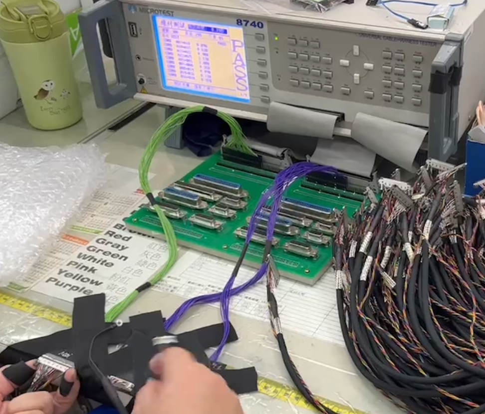
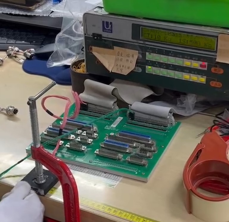
Every NAVITAS custom cable assembly is electrically tested during production. That means 100% of units, not a sample. Each assembly is tested on dedicated test equipment and checked against its programmed wiring map. Different products use different testers and dedicated fixtures: Figure 1 shows D-Sub assemblies on a MICROTEST 8740N, and Figure 2 shows an M12 cable assembly on its own test fixture.
Standard tests depend on the product line. For wire harnesses and industrial custom cable assemblies, four tests are standard:
- Continuity: every intended circuit conducts
- Short circuit: no unintended connections between conductors
- Miswire: every pin connects to the correct pin
- Insulation resistance (IR): insulation between isolated circuits meets the required minimum, measured at a DC test voltage
IR test conditions follow our internal standards, set by product type and cable rating. When a customer specifies different conditions, we first confirm that the design can meet them, then test to the customer's specification.
Hi-Pot (dielectric withstand) testing is not part of this standard four-test process.
For RF coaxial cable assemblies, continuity, short circuit, insulation resistance and Hi-Pot testing are performed on 100% of units.
Only assemblies that pass all standard tests for their product line move on. If your application requires specific test conditions, include them in your RFQ, and we will confirm feasibility before production.
Stage 2: Pre-shipment sampling inspection
Before shipment, a separate sampling inspection is carried out against the approved drawings and specifications. It covers:
- Overall and branch lengths against drawing tolerances
- Cable and connector part numbers against the drawing
- Wire color order and cable tie positions
- A repeat continuity check on a test fixture
- Visual and push/pull checks: heat-shrink retention, conductor damage, insulation seated under the terminal, housing type and contact position
An inspection report can be provided upon request.
Where electrical testing stops
Electrical testing confirms that an assembly is correct and electrically sound when it leaves our production line. It does not replace application-specific validation, such as flex life, vibration or temperature testing, or ingress protection validation. It does not replace engineering decisions on cable selection, strain relief and routing either. We review these points with customers during engineering review, before production starts. That is where many of the failure modes described above are prevented most effectively.
What Buyers Should Specify Before Production
The clearer your requirements, the more closely testing will match the real risks in your application. Before production, define:
- Which electrical tests are required on 100% of units
- IR test voltage and minimum insulation resistance
- Hi-Pot test voltage (AC or DC), dwell time and maximum leakage current, where applicable
- Whether test records must be retained, in what form and for how long
- Application conditions: flex cycles, vibration, temperature range and IP rating
- Mechanical verification: pull force values and crimp cross-section requirements
- Labeling and lot traceability requirements
If you are unsure about a value, describe the application. A good supplier should be able to propose test conditions and explain why they fit.
Conclusion: Reliable Cable Assemblies Begin Before Final Testing
100% electrical testing is essential. It catches wiring errors, shorts and insulation defects before an assembly reaches your production line. But testing confirms quality at a single moment. Reliability in service is decided earlier, through design review, controlled processes and validation that matches the real application. When you evaluate a cable assembly supplier, ask both questions: which tests do you run on every unit, and how do you prevent the failures those tests cannot see?
Discuss your cable assembly testing requirements with NAVITAS. Send us your drawing and application conditions, and our engineering team will review test requirements with you before production.
Frequently Asked Questions
Does 100% electrical testing mean every cable assembly is fully qualified?
No. "100%" means every unit is tested. It does not mean every characteristic is verified. Electrical tests confirm correct wiring and sound insulation at the time of manufacture. Long-term performance under flex, vibration, temperature or moisture requires design review and application-specific validation.
What is the difference between an insulation resistance test and a Hi-Pot test?
An insulation resistance test applies a DC voltage and measures how much resistance the insulation provides, typically in megohms. A Hi-Pot test applies a higher voltage for a defined time and confirms the insulation does not break down or leak excessive current. The IR test shows insulation quality. The Hi-Pot test shows withstand capability.
Can a cable assembly pass electrical testing and still fail in the field?
Yes. A marginal crimp, conductor fatigue, abrasion caused by routing, or water ingress can all develop after an assembly has passed electrical testing. These risks are controlled through process checks such as crimp and pull force verification, design review and application testing.
What should I ask a cable assembly supplier about testing?
Ask which electrical tests are performed on every unit, under what test conditions, what is checked during pre-shipment inspection, and what records are kept. Asking only "Do you test 100%?" does not tell you which tests are included. For applications that require Hi-Pot testing, confirm the test method and acceptance criteria before placing an order.
Sources
- Directive (EU) 2024/2853 on liability for defective products — EUR-Lex
- Corrigendum to Directive (EU) 2024/2853, 7 May 2026 — EUR-Lex
- NHTSA recall 26V547000 — Ford Mustang
- NHTSA recall 26V096000 — BMW
- NHTSA recall 25V769000 — GMC Hummer EV
Regulatory and recall information last verified: .